Team lead, Formula Electric at Berkeley FSAE 2022
I led the Design, Manufacturing, and Validation (mechanical) of our maiden battery pack, which succeeded in passing technical design inspection.
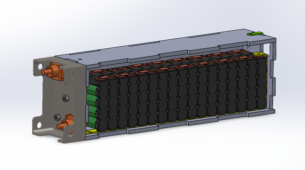
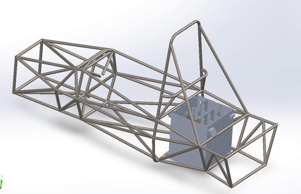
This is the final conceptualization of my design, which is the culmination of a year of R&D, testing manufacturing methods in-house, and collaboration with the EECS team to ensure we were able to easily wire up our components. However, this was not the final design we produced… (story time)
Initial design cycle
The design cycle began in Aug 2021, with the beginning of fall semester. I had just joined Formula Electric at Berkeley, and the club was moving full steam ahead to produce our first car. Understandably, things were chaotic. As I began work conceptualizing and developing the battery pack, there were a few key factors that obstructed my progress:
- The spaceframe (chassis) had already been finalized so that we could order the tubes (prior to me joining the club), which meant that the space we had for mounting the battery pack had been decided before we could properly dimension the pack. We used 18650 cells from Energus
- The series and parallel configuration of the modules (individual batteries arranged to provide the required voltage/current to power out motor – 560 V) had not been finalized.
- The other subteams already had components in the spaces available for routing potential cooling paths.
- I didn’t really know what I was doing. F

Pack configuration
We came to a consensus on using a 17 x 8 module configuration in order to obtain our required voltage and current output. Then I began to design and package each segment
4 cells (3.6V), making a module, producing 3.6V in parallel, 12.4 Ah
17 modules in series, making a segment, producing 17 x 3.6 V segments – 61.2V
8 segments in series, making a pack, producing 8 x 17 x 3.6V – 500V, 12A
Now I had to design each segment to house 17 modules, and then decide how to make 8 of them for our complete pack.
Initial Segment Design
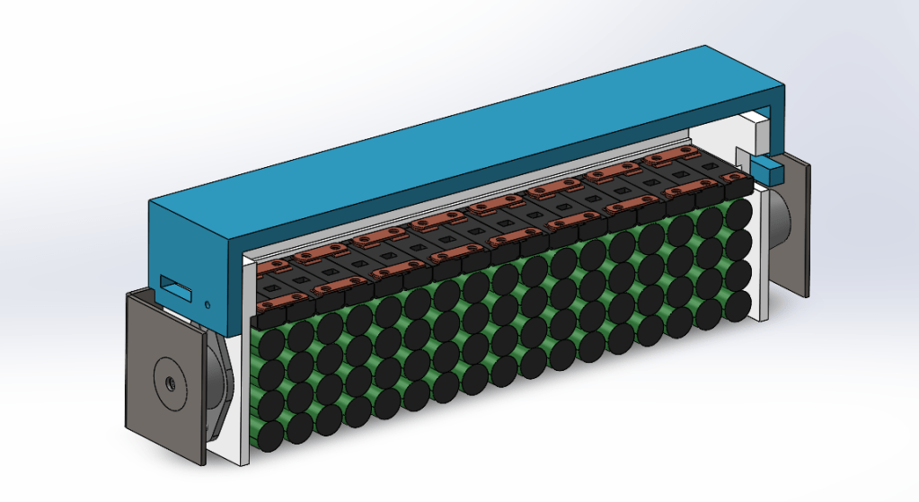
I began by analyzing the dimensions of each module, then scaling it to accommodate each 17-module structure.

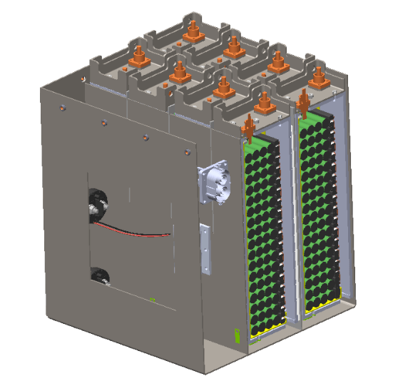
I initially chose PLA as the material to create the segment enclosure as I had worked with PLA in 3D printing. With this in mind, I created, after a few design revisions, a completely 3D-printed segment. The design includes copper bus bars, rubber vibration dampers (to absorb cyclic loads from the car riding on the road), and metal restraints for mounting inside the whole pack casing. I left space on top of the bus bars for circuit boards (BMS) and wiring. The casing relies on the lip that runs around each module in order to have a load path that avoids the circuit boards.

One thing I did not realize was that PLA warps at 60C which is the max temp for the battery pack, so I decided to get the segment made out of ABS which has a warp temp of 120C, much better!
Initial Pack Design (Parametric modeling)
Now that I had a rough segment size, I could work on fitting the pack into the spaceframe. However, that proved incredibly challenging, as we as a team could not come to an immediate decision on what dimensions the casing should be to best accommodate for mounting, the center of gravity of the car (the pack weighed >10% of the car’s weight) and to avoid interfering with other subteams’ components.
This was frustrating as every time we wanted to test a different configuration I had to go through every sheet metal component and update the dimensions to fit the new constraints.
To solve this I decided to use parametric modeling (creating a model according to equations), which although it took a while to set up, improved our workflow much more efficiently.
Link to Video (skip to 50 seconds)
We settled on a 4 x 2 vertical segment configuration to allow for ease of wiring, mounting and minimal interference with other subteams.
Rules and Constraints
FSAE rules stated the pack had to withstand 40G lateral and longitudinal deceleration, and 20G vertical deceleration (simulating a crash and roll) in order to sufficiently protect the driver from the batteries combusting under impact.
Li-ion batteries are highly susceptible to battery fires and are extremely flammable. If a short circuit occurs as a result of a collision, the batteries would go into thermal runaway and ignite rapidly, putting the driver at risk.
A lithium-ion battery consists of an anode, cathode, and electrolyte as well as a separator, see Figure 2.1. The anode is the oxidized electrode that removes electrons from the external circuit during discharge. Correspondingly, the cathode is the oxidizing electrode that receives electrons from the external circuit. The electrolyte is the medium to transfer ions between electrodes inside the cell and the separator is used to isolate electrodes.
Rules
- 40G deceleration laterally and longitudinally, and 20g deceleration vertically (26kN from 66Kg accumulator)
- Fixtures at minimum 8 corners from casing to the spaceframe (welded aluminum mounts)- in order to conform to load-based mounting
- Longitudinal load case application (worst case)
- 6Kg segment * 9.81 * 40 applied on each parallel divider wall
- Gravity * 40 to simulate housing deceleration
- Worst case as it is a direct line of driver
- Lateral load case
- The same load applied laterally with lateral gravity
- Vertical load
- Segment loading the internal dividers in shear at 20g
- Gravity vertically * 20
Casing Design
In order to meet our rules constraints and be manufacturable, I had to consider:
- Load cases – can we withstand the multiaxial loading?
- Materials selection – would steel or aluminum be better to meet sheet metal minimum thickness
- Weight – The car has to be under 750 Kg, the pack between 50 and 80Kg
- Assembly process – how would the internal and external structures be put together
- Mounting – how would we attach it to the chassis
- Ingress proof – water + battery = no good
- Cooling, thermal management
- COST – we’re a student team. Enough said.
After a few iterations of design, I had the right dimensions and began testing the casing.
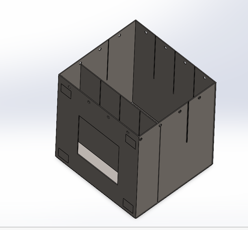
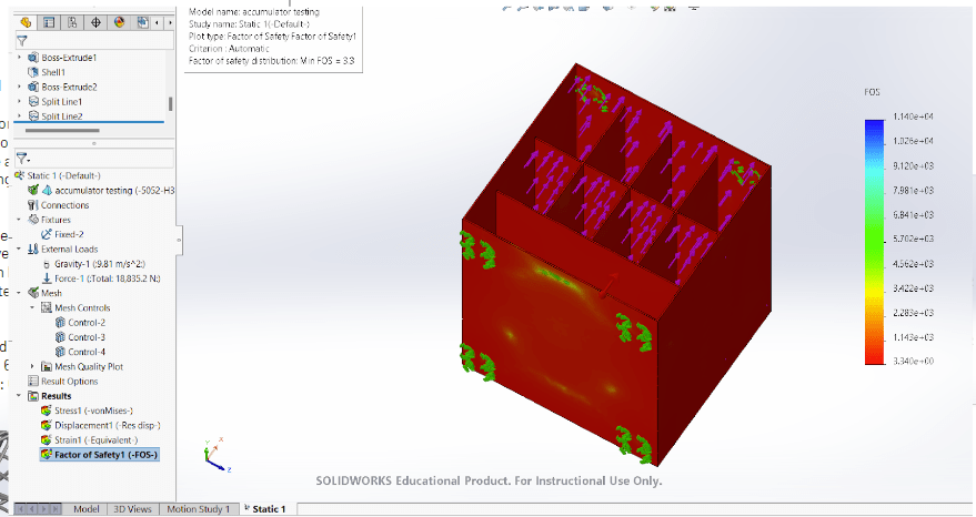
Initially, my solutions to the aforementioned considerations were to use 2mm thick steel 1020 sheets to create a rectangular casing with internal dividers to increase surface area to spread internal loading from the segments decelerating, as well as isolating the segments from each other. It was HEAVY (75kg) according to Solidworks, and my assembly process was to use tabbed slots that would be slid together.
We planned to outsource the entire casing for manufacture.
Reasons for choices
To withstand the 40G loading with minimum center deflection (to prevent fracture and penetration of cells) I chose steel because of its high strength and stiffness properties.
40 x 9.81 m/s^2 (Gs) x 20kg (casing weight) x 8 x 6kg (segment weight) = 63KN
This was the max conceivable loading on the front-facing sheet metal plane (given internal structure failure) which would be the worst-case situation, and had to be addressed to prevent harm to the driver.
The max stress therefore = 63KN / (0.175 M^2 area) = 360KPa.
The UTS (ultimate tensile strength) of 1020 steel before it would start necking is 400MPA, thus we were well within the limits of elasticity and would have minimal deflection.
I validated this using FEA (Solidworks) and got a very high Factor of Safety – 33
Tabbed slots seemed the most practical for the manufacture of each seperate piece of sheet metal, following which we intended to butt weld the seams to make it water tight and ingress proof.
This was all wonderful, and we planned to outsource the pack for manufacturing so we didn’t have to risk making errors with our slightly suspicious manufacturing skills.
Problem!
It is way too heavy. Our mounts were going to have to be incredibly beefy to support the weight of the complete pack.
Steel is tough and makes tools wear down fast, and if we were going to machine it in house that would be very bad. Especially if we’re drilling holes for ventilation because the waterjet is expensive and charges by the minute. Laser cutters struggle with 2mm thick steel.
Solution!
Switch to Aluminium. Make the walls thicker.
After adjusting the dimensions to increase thickness (3.5mm wall) on Solidworks, Aluminium proved to be 20 KG lighter than steel for an equivalent (slightly lower) strength rating, though still within our restrictions. Aluminium is more ductile than steel is, and has a lower yeild strength, but has a far higher strength-to-weight ratio than steel, thus proving itself valuable for our purposes. Re-running the FEA gave us a FOS of 5.5, which was perfectly adequate.

Aluminium is tougher to weld than steel because it has a higher specific heat capacity, and requires more precise puddle control, so we still planned to outsource manufacturing.
Success! WE SENT EVERYTHING OUT FOR MANUFACTURING
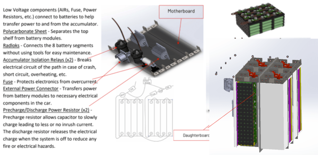
Thermal Management
Battery packs get hot. Every battery has a small internal resistance, which is generally the resistance of the electrolyte. As current flows through the batteries, power is consumed by the internal resistance and generates waste heat. Batteries operate in an optimal temperature range of 40 to 60 degC, and have to be kept within that range to prevent the PTC switch from over heating and shutting down the pack for safety.
Operating at full capacity and highest load (worst case), we expected to run 3 Amps through each battery for an hour – 3Ah = 3C. IF we assume an internal resistance of 200 miliohm = 0.2 ohm per battery:
P = I^2 x R
P = (3^2 x 0.2) x 136 = 244 W of heat energy generated in the pack
If 244 W of heat is generated with the pack operating at 6KW (500V x 12A), we lose close to 5% of power to heat.
All this heat has to be quickly dissipated to the environment in order to prevent the temperature of the pack rising above 60 C.
Methods of cooling a battery pack
Packs are traditonally cooled in three ways:
- Air cooling – forcing air through streamlines in the pack to carry heat away
- Liquid to air cooling – using coolant to absorb heat and then cooling the coolant using a large radiator and fan
- Liquid to liquid cooling – using refrigerant and a chiller to actively control the temperature of the pack
We decided to go with forced air cooling because we had no room for mounting a radiator, limited time to produce cooling tubes, and a pack that wasn’t quite right yet. Air is much easier to work with.
To do this I planned to have an inlet and outlet to guide air through holes in the casing assisted by high static pressure fans in order to reach a mass flow rate that would be adequate to provide enough cooling for the pack.
Air flow rate calculations
Heat rejection required = 244W
Cp specific heat (since no pressure change) of air = 1KJ/Kg
Q = MC dT
244 J = M x 1000 J/Kg x dT
I assumed a dT of 10 degC to keep the pack at 50 C from a max temp of 60C
M = 244 / 1000 * 10 = 0.0244 Kg of air-flow per second through the pack
Volume of air per second = 0.0244/1.27 Kg/M^3 = 0.02 M^3 of air-flow per second – achievable values using 8 high static pressure fans
More indepth calculations should include the conductive coefficeint of the battery skins, the loss in pressure as air moves along the channels and stagnation, but this was a good enough estimate for our purposes
Problem
- We bought the wrong fuses, so we couldn’t even run at our max values
- How do you prevent ingress through ventilation ducts?
- Where to route inlets and outlets
Solution!
No cooling! No need to worry as the batteries won’t produce enough heat as they can’t run at max capacity and therefore can be simply kept cool by chilling the whole pack in the fridge beforehand. Neat!
No need to worry about ingress either – however, we would have used hydrophobic mesh, BTU to seal the seams, and a U bend to rapidly decelerate the air – creating a high-pressure zone to cause condensation.
Mounting
Mounting was a major concern, as I had to consider load-based mounting on 8 corners and specifying thick enough bolts to have double shear with a high enough shear strength rating to prevent shear failure. I did the following
- Simulations on mounts run to test extreme load cases
- 8 corner-based mounts in double shear with 10mm bolts: chassis side made of AISI 1020 steel, accumulator side made of 5032-HB Aluminium
- Each mount tested at 8335N (higher than required) to account for deceleration of 40G in all directions
- Standard accumulator side mount (dim: 20mm * 25mm * 20mm) welded to the skin of the accumulator within 50mm of each corner, and in close proximity to chassis nodes
- Chassis side mounts symmetric across the center of accumulator – welded to spaceframe bars (2 mounts per bar)
- Specific mounting geometry to allow the accumulator to be slid in from underneath the chassis.
I designed each mount to fit on a different tube on the chassis, at varying radii in order to keep the pack roughly parallel to the ground.
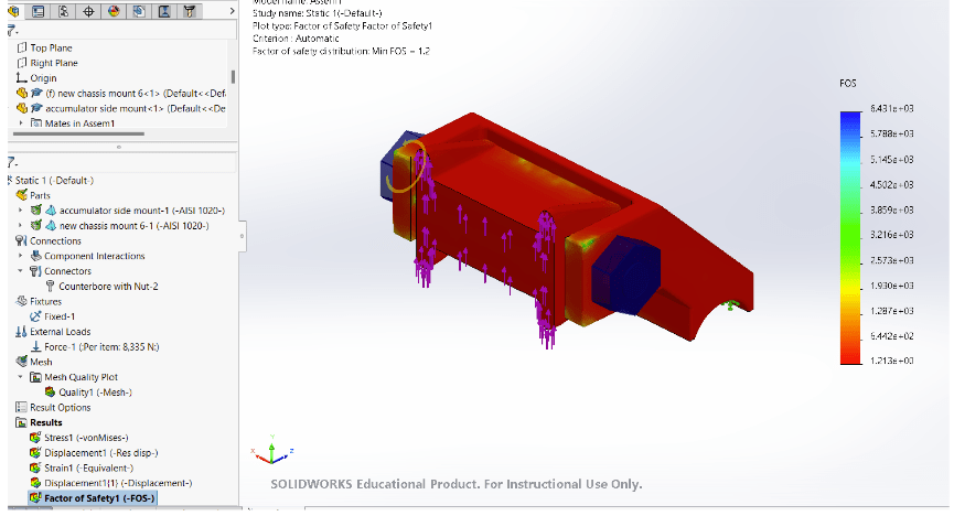
Success! We ordered the mounts from Protolabs, paying a hefty (sponsored) price to get them beautifully machined.

CRISIS
In the last 2 WEEKS before competition we found out that our shipping company LOST the package with our entire mechanical battery pack….
All the segment components, casing and connectors were gone.
We had to think fast and manage the crisis with what we had available to us – a water jet, laser cutter and half decent aluminium welding.
It was a week from hell, with final exams around the corner, me, and my team worked till 4 am redesigning and manufacturing all the components out of material available to us.
Segment redesign
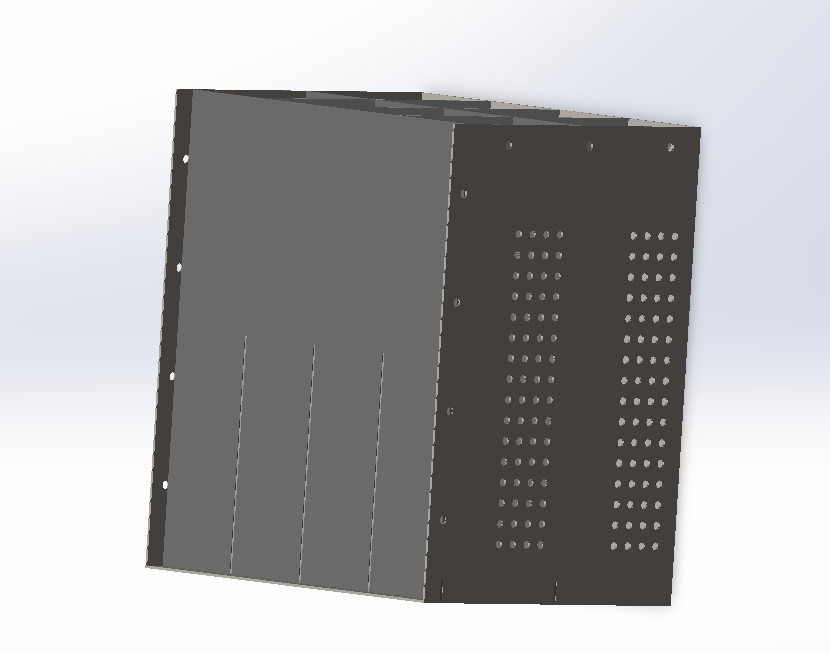
I completely redesigned the segment (previously printed in 3 pieces of ABS) to be made really fast (we had to make and assemble 8) and with a laser cutter! This is made out of 1/8th in acrylic, slots together and was held with acylic glue.
We had to fabricate custom busbars, which I designed with a bend radius that we could make on our machine shop metal bender, but still with enough thickness to carry 12A

I made new wiring connector headers which we printed on a Formlabs (fancy) and got 8 made just in time.
Casing redesign
I redesigned the casing to be manufactured in our machine shop using the water jet to cut out sheets of aluminium so we could weld them together after tabbing them to slide together.

I made all our pack side mounts uniform so we could machine them using a CNC mill, making 8 mounts for the corners.
We also increased the space available for wiring to held with wire routing, by modifying the circular cut out geometry to prevent chamfer and damage to the wire insulation, and also to allow for larger bend radii in the cables.
IT was TOUGH but we persevered!!
Final assembly
Casing (slightly warped from welding)


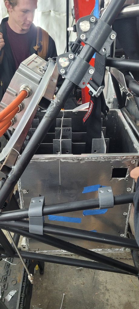
Since the casing warped during welding it threw our mount tolerances completely off, which I hadn’t taken into account when designing the mounts. Next time, I will definitely accomodate for unforseen errors by leaving a larger functional zone.
Completion of (I believe) a successful design cycle!
